Please review the site Rules, Terms of Service, and Privacy Policy at your convenience. Rules, TOS, Privacy
Get familiar with the reaction system: Introducing the Reaction System

XO Design for MDF MCM MTM

XO design for the MCM MTM.

I tried out a preliminary XO and am getting third order for tweeter and fourth order for woofer. Need a quick reivew on the XO and if possible any optimizations of suggestion for improving. The XO file is attached in this link, please feel free to play with it: 
https://drive.google.com/open?id=0B2bbY-YB6ikpWk13VVhxc1FEQVE

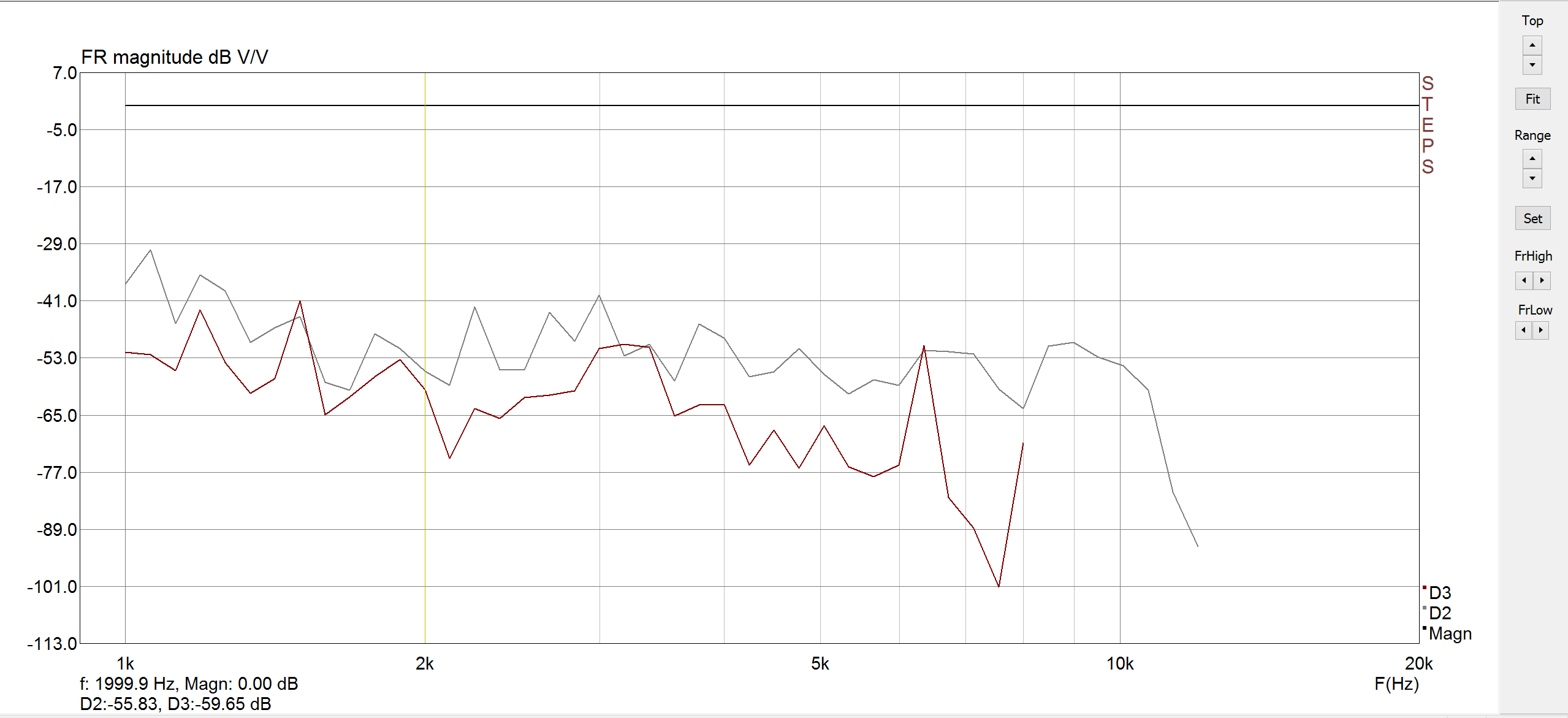
The XO point is 2k, the tweeter distortion measurement is here: https://diy.midwestaudio.club/uploads/editor/h8/lf5zgonqd6q7.png
Some discussion about the tweeter can be found in this link: https://diy.midwestaudio.club/discussion/341/broad-depression-in-tweeter-response-7-8khz

XO Screenshots:


«1

Comments

  • Any particular reason you are not using any compensation for the baffle step, Ani?
    I have a signature.
  • edited June 2017
    The measurement is taken free air, away from all wall (min 4 feet), so it that is needed then how do i add it? Just tilt the response down, i wasn't sure where and what to add due to the squiggles in the response all over, it is +/- 3-4 db all throughout.
  • ok, added a bit of BSC, and have two versions. Please let me know which looks better from a graph point of view, or if i need to add more. What do you look for in a BSC and are there any rule of thumb?

    V5:


  • V6: Slightly different BSC. Is this better or we need something else....


  • I like the 2nd one better. 
    I have a signature.
  • I agree with JR, the second one is certainly better, but in my opinion it will still be too forward and hard to listen to long term.  I know we as DIYers want to be as meticulous as possible and see (correct) every dip, blip, and peak;  i.e. super high resolutions on our measurements.  But sometimes a little good old smoothing on the measurements (like 24th octave) helps show the big picture.
  • Ani, quick tip is to look at your woofer transfer function curve. It should be about 6db down above 800-1000 or so. Transfer function isnt the absolute authority, but can help get you there. 
    I have a signature.
  • Then, as Craig says some smoothing and a gate would not hurt, either. 
    I have a signature.
  • Can we smoothen in PCD? Or smoothen the measurement after XO? I'll try getting it down to 6 db... Might have to zoom in a bit.

    When you say forward, does it mean the high are still playing higher and should be taken down a bit? I have a bit more downward tilt right to left on the charts?
  • PS I do have a gate around 200hz...
  • One more try.

    V6 XO, more aggressive BSC, and the tweeter response is also tilted down. Now the issue is if I have all those tiny inductors on hand....


  • edited June 2017
    Have you tried any of these xo's? Have you tried a 2nd order? I ask because I like 2nd order in a 2-way.
    Hell, I just like 2nd order.  :p

    ............. could you hum a few bars.
  • I did try second order, but couldn't keep the woofer breakup down enough. With the requirement to cross higher and squash the breakup I need a steep roll off on the woofer.

    Are you asking for second order on woofer or tweeter or both?
  • No I haven't tried these XO yet, but am putting it together today depending what parts I have on hand.
  • Ani, one old trick to reducing parts count while hammering a woofer breakup into submission is to use a circuit such as this:


    Expect to do a little experimenting with that capacitor paralleled around the main woofer coil. You will likely find that a high parts count is not necessary for the woofer circuit. 

    D1PP1Nkennyk4thtry
    I have a signature.
  • I know, my electrical CAD engineering chops are second to none. 
    Turn2Nicholas_23kennyk4thtry
    I have a signature.
  • Actually much clearer than Wolf's multi colored schematics :)
    D1PP1NNicholas_23kennyk
  • Thanks JR, i'll try that and am working on a 2nd order on the woofer and 3rd on the tweeter.
  • What's up with phase? I see they track each other nice, but the rotation doesn't happen where the xover is happening? I've never seen that?
  • 6thplanet said:
    What's up with phase? I see they track each other nice, but the rotation doesn't happen where the xover is happening? I've never seen that?
    I don't think I understand that. What i am looking for and what should be happening?
  • To get the woofer to 3K I like a small inductor for the knee then a larger inductor notch for the BSC.  I'd also do the tank on the break up, although this is not really possible to show in PCD.

    The filter would look something like this, sorry I can't do legible sketches...

    I also noticed the PCD measurement distance was set at 2 meters?


     John H, btw forum has decided I don't get emails
  • ani_101 said:
    6thplanet said:
    What's up with phase? I see they track each other nice, but the rotation doesn't happen where the xover is happening? I've never seen that?
    I don't think I understand that. What i am looking for and what should be happening?
    Most times the phase rotation (where the phase appears as a vertical line or lines) occurs at the crossover point. It's not unheard of not to be at thst point however. 

    It can be an indicator of a LR alignment with the reverse null. Someone please correct me if my thinking is not on par.
  • The raw driver phase appears to flip a few times which can be an indicator of non-minimum phase files.
     John H, btw forum has decided I don't get emails
  • Yes you are correct Chuck.  The point of phase rotation on the graph isn't important.  The actual phase tracking of the drivers through the xo area is.  Reverse null is a good indicator with LR4 slopes, but is never as defined or deep and narrow with shallower slopes like LR2.  And my measured reverse nulls never look as pretty as my simulated ones.  Playing in "Sim Land" I find that the difference between 0.13 mH and 0.14 mH on a tweeter shunt can have a huge effect on the simulated reverse null.  But in real life (sorry Chris Romer) the difference is mute.
  • The raw driver phase appears to flip a few times which can be an indicator of non-minimum phase files.
    It is actual ZMA taken with DATS for tweeter and the pair of woofers in parallel and then min phase extracted in response modeler before loading into PCD.

    But I do think the mic distance is wrong, it is not 2 meters, i will measure the distance and correct it and try out JR's and your suggestion on the XO.
  • ok, changed the PDC measurement distance to 1.32meters, which is the actual measured distance...

    this is my second order o nthe woofer, breakup still stere, about 25db down, would have liked it further squished down, but will try adding a small cap across the L2 inductor and measure and change and measure and see if it makes a difference on the woofer response.

    John, I am not able to follow your instructions in PCD. Could you kindly elaborate what i can simulate in PCD and which component I need to experiment with?

    V8:

  • Ani, if you use the notch in PCD you can not do the tank to my knowledge.  Try these values in the picture.

    I'm sure it's a typo but you are extracting minimum phase from the FRD files. The minimum phase files and your x and y offsets and your measurement distance are entered in PCD to find your z offset.


     John H, btw forum has decided I don't get emails
  • Reduce the 2uf to .33 and the resistor input 99999999. Pcd will see it as infinite.
  • OK, this is the final XO i got, that will (hopefully) make it tomorrow to SD along with the multi-colored wires. Thanks for the different pointers and tips. I combined some of the tips and changed values and measured and selected the one which looked good enough then did some listening again while changing, adding, removing components, and this one seemed to be the most promising.

    Woofer XO:


    Tweeter XO:


    Measurement:

  • I really thought these sounded great at DDIY, fwiw. They needed just a touch more of baffle step IMO, but where very close to perfectly balance. I apologize if I misheard you Ani and played my demo instead of JRs, but getting to listen to my own demo made it very clear to me you nailed the crossover integration.

    I looked for a driver measurement and found this: https://www.hifisound.de/Do-it-yourself-Products/Speaker-Drivers/Low-Midrange/Gradient-Select-W-130-AL-8-Shielded-Aluminium.html It seems to have a downward slope already, hence the need for less baffle-step in the crossover.
    = Howard Stark: "This is the key to the future. I'm limited by the technology of my time, but one day you'll figure this out."
Sign In or Register to comment.